


The Swedish Heterodyne Facility Instrument
|
|
|
|
|
Introduction
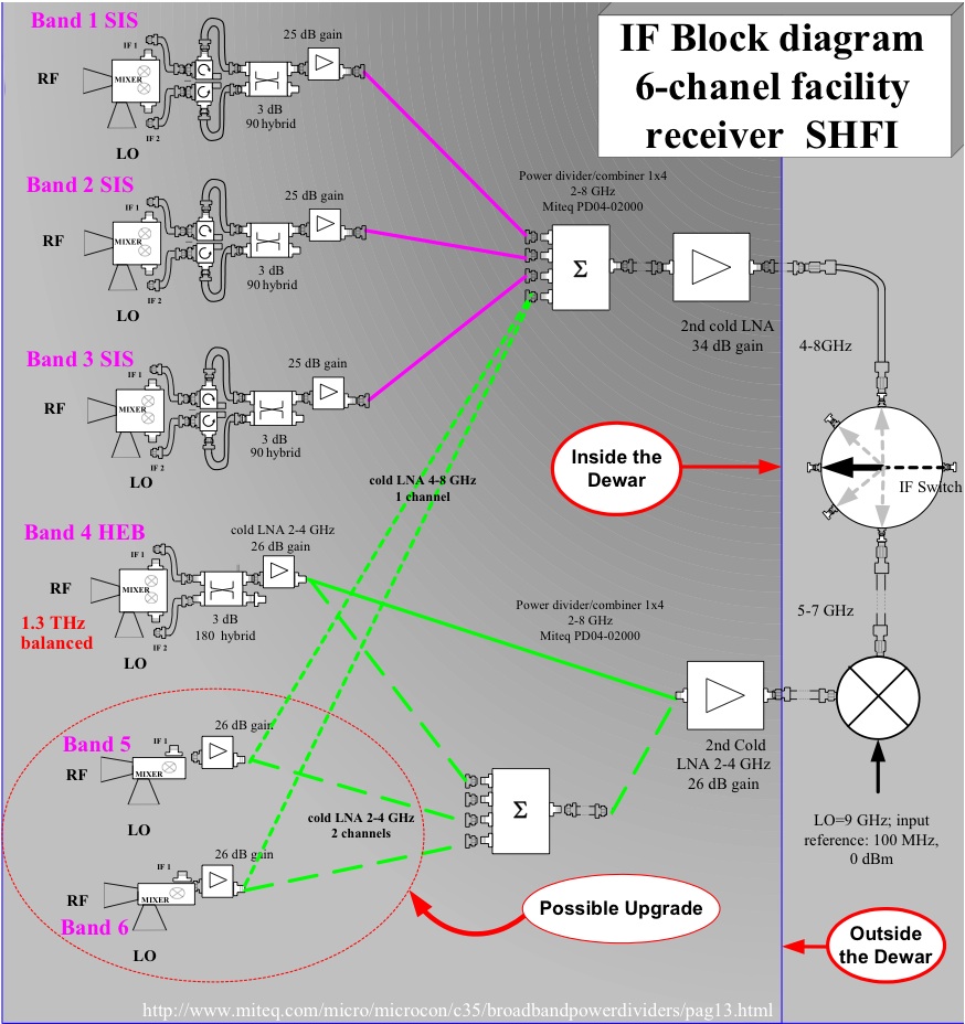
The Swedish Heterodyne Facility Instrument (SHeFI) was built by the GARD group at the Chalmers University, Sweden, with the Onsala Space Observatory. A SHeFI webpage which may contain complementary information is maintained there. The SHeFI consists of four wideband heterodyne receiver channels for 230 GHz (APEX-1), 345 GHz (APEX2), 460 GHz (APEX-3), and 1300 GHz (APEX-T2). All the bands are located inside a single closed-cycle cryostat which maintains the coldest part at a temperature close to 4 K. The first three bands for 230, 345, and 460 GHz employ superconductor-insulator-superconductor (SIS) mixers and behave as single sideband receivers (SSB). The 1.3 THz band is built using hot electron bolometer (HEB) mixer technology and is a double sideband receiver (DSB).
The Cryostat/Cryogenics
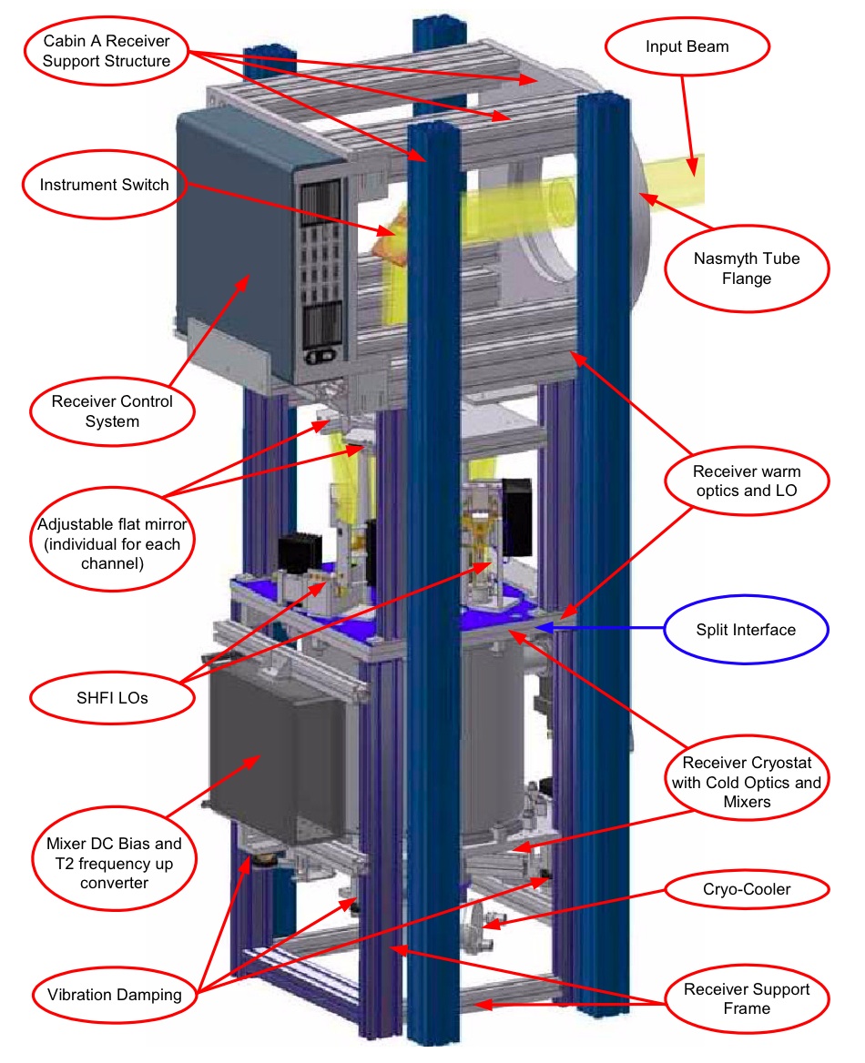
The SHeFI receiver is located in the Nasmyth-A cabin of the telescope. The optical path is fairly complex and includes not less than 11 mirrors including the main dish and the subreflector. The SHeFI receiver support structure is firmly attached to the Nasmyth elevation tube flange and therefore temperature deformations of the A cabin have little effect on the receiver alignment.
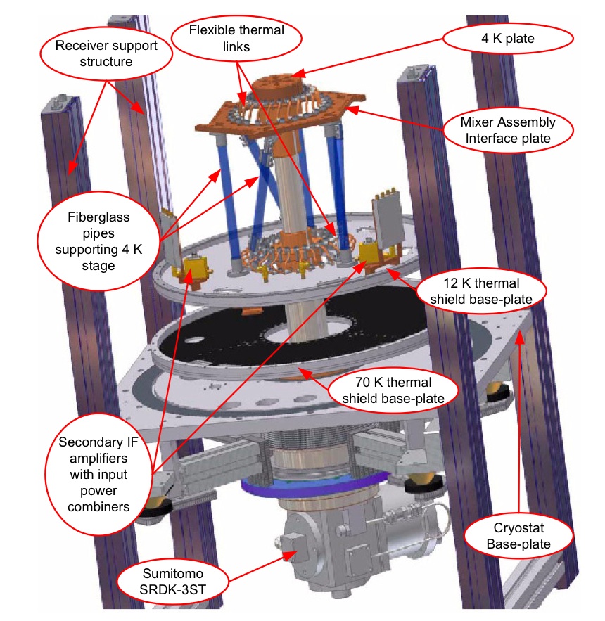
The cryostat was built at the Chalmers University and uses a closed-cycled Sumitomo cooling machine providing temperatures at the coldest stage below 4 K, which is needed for the best operations of the superconduting mixers.
It is only possible to use one receiver band at a time. A rotating mirror selects the desired band. Therefore, there is only one intermediate frequency (IF) cable going to the backends (XFFTS and total power). The switching time from one band to another takes less than 5 minutes, temperature stabilization of LO chain and mixer block included. These heterodyne instruments all use for the local oscillator (LO) injection, direct multiplication chains. The reference signal comes from an HP signal generator providing a strong clean signal from 10-20 GHz.
Receiver bands
| Instrument | Type | Mode | Frequency [GHz] | HPBW [arcsec] | IF range [GHz] | # of beams | Location | Status | Comment |
|---|---|---|---|---|---|---|---|---|---|
| APEX-1 (SHeFI) | Heterodyne SIS | SSB | 213 - 275 | 30 - 23 | 4 - 8 | 1 | Nasmyth-A | ||
| APEX-2 (SHeFI) | Heterodyne SIS | SSB | 267 - 378 | 23 - 17 | 4 - 8 | 1 | Nasmyth-A | ||
| APEX-3 (SHeFI) | Heterodyne SIS | DSB | 385 - 506 | 17 - 13 | 4 - 8 | 1 | Nasmyth-A | APEX-T2 (SHeFI) | Heterodyne HEB | DSB | 1250 - 1390 | 5 | 2 - 4 | 1 | Nasmyth-A | Science Verification pending |
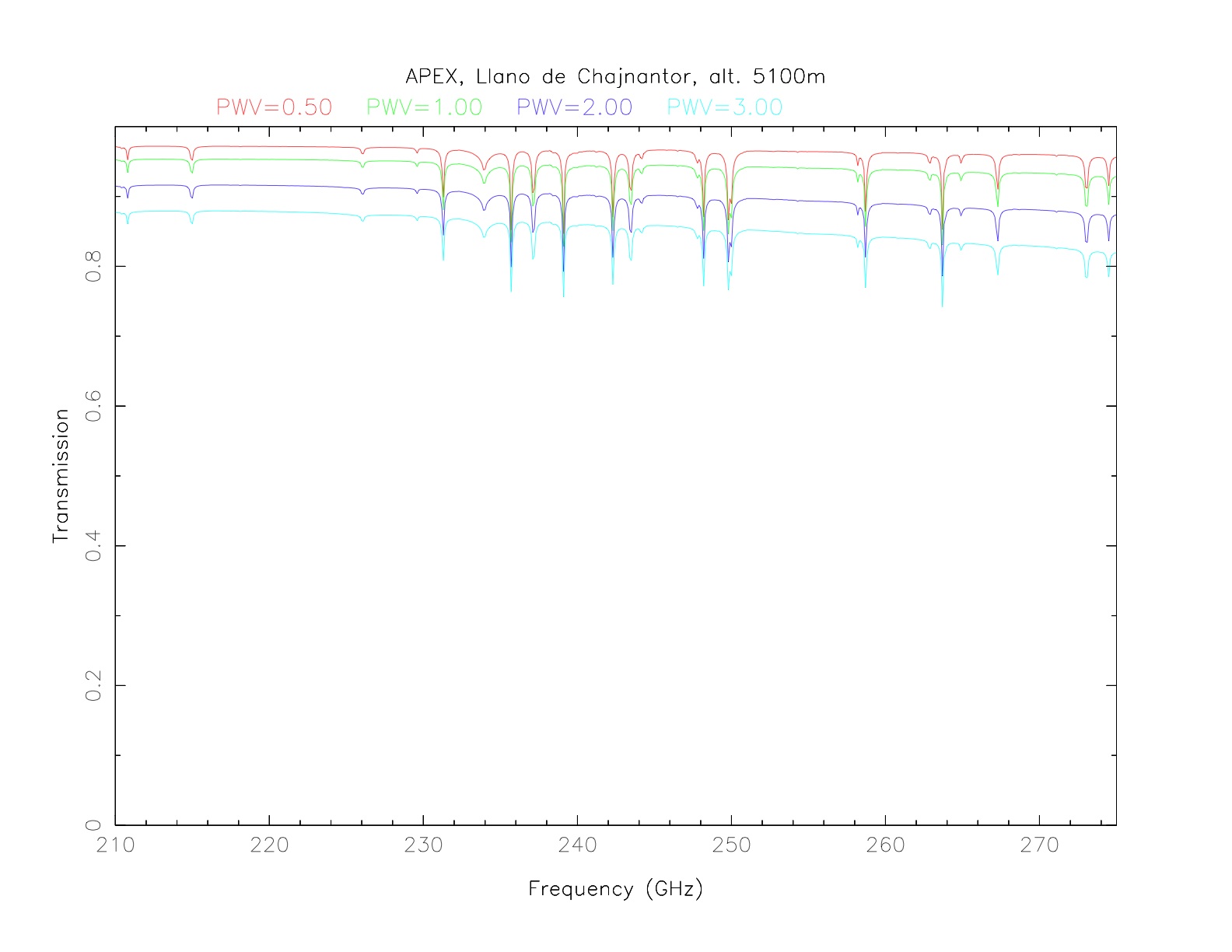
- APEX-1.
It is an SIS heterodyne receiver operating in the band 213-275 GHz. At those wavelengths, the atmospheric transmission at APEX allows good observations until a precipitable water vapour (pwv) of ~4 mm. For receiver temperatures see APEX-1 characteristics. It operates in single sideband (SSB) mode using sideband separation mixers. The SSB rejection is >10 dB over the entire band. The IF range is 4-8 GHz. - APEX-2.
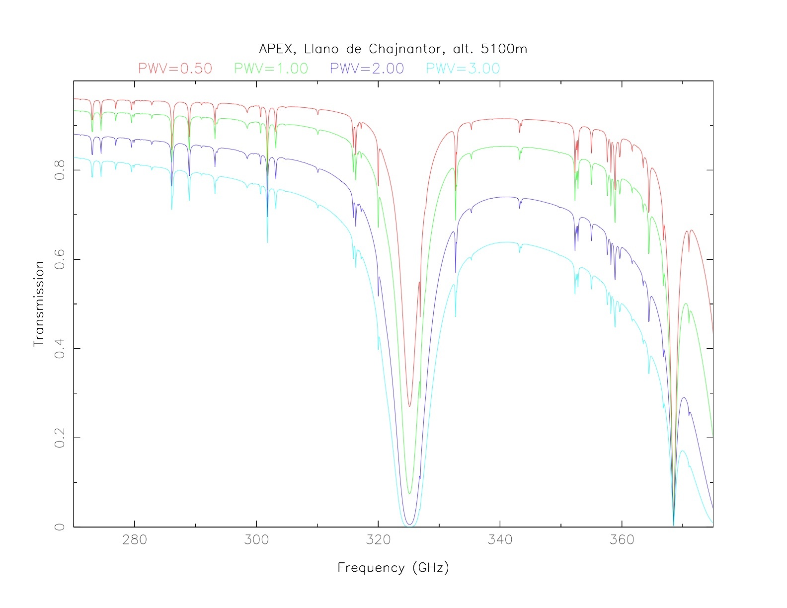
It is an SIS heterodyne receiver operating in the band 267-378 GHz. At those wavelengths, the atmospheric transmission at APEX allows observations until a pwv of ~2 mm. For receiver temperatures see APEX-2 characteristics. It operates in single sideband (SSB) mode using sideband separation mixers. The SSB rejection is > 10 dB over the entire band. The IF range is 4-8 GHz. - APEX-3.
APEX Band 3 is a DSB heterodyne SIS mixer receiver covering frequencies 385-506 GHz. - APEX-T2.
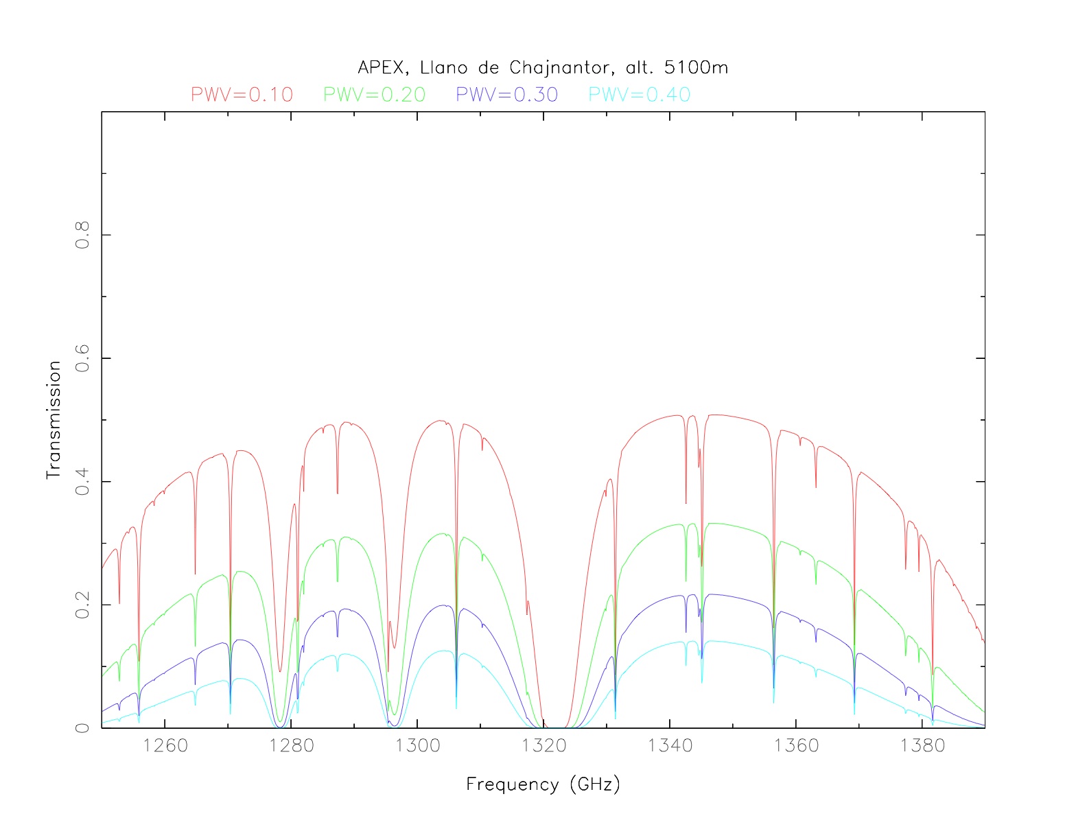
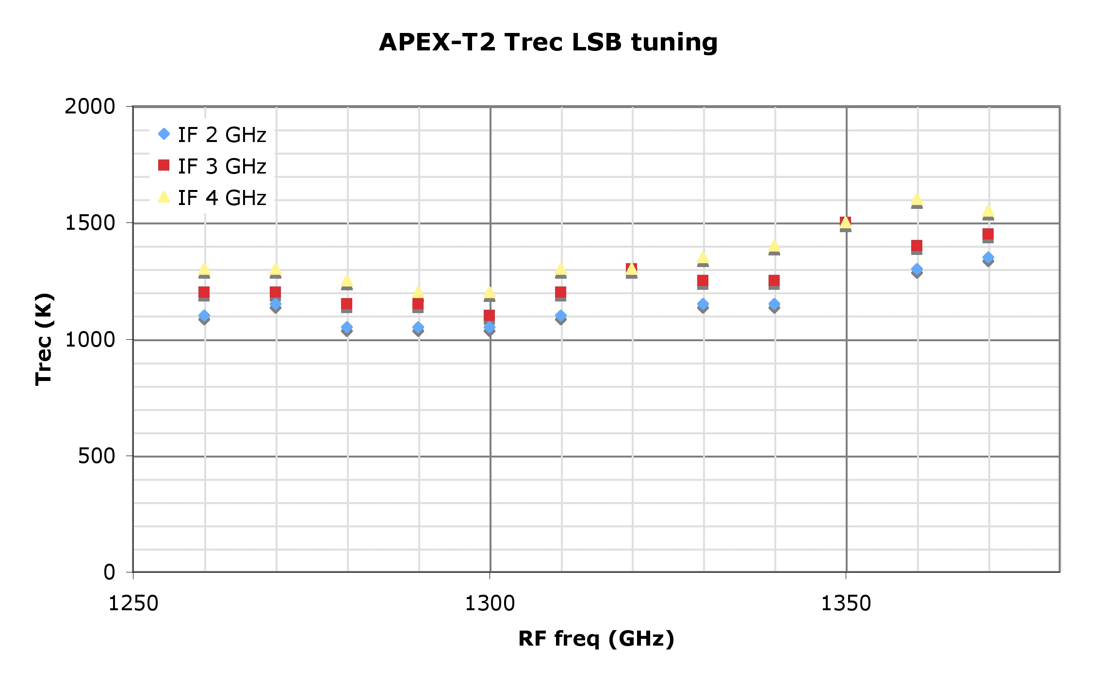
It is an HEB heterodyne receiver operating in the band 1250-1390 GHz. At those wavelengths, the atmospheric transmission at APEX allows observations until a pwv of ~0.3 mm. For Trec see APEX-T2 Trec LSB tunings. It operates in double sideband (DSB) mode and uses balanced mixers. The IF range is 2-4 GHz.
Observing modes and patterns
Switch modes
- Position switching
In position switching mode the telescope moves between the ON-position and a user-defined reference position. Since APEX can move fast, reasonably stable baselines can be achieved under normal weather conditions. The reference position can be given in relative coordinates (to the catalog source position) or in absolute coordinates, in the horizontal or equatorial system. Integration times at ON- and OFF-positions can be different, and a number of different ON-positions can be observed using one OFF-position. - Beam switching
By using the wobbling secondary it possible to switch rapidly between positions up to 5 arcmin apart on sky without moving the antenna. - Frequency switching
This switch mode is not (yet) implemented.
Observing patterns
- On-Off
Observations of a single position in any of the available switch modes. - Raster map
In raster mapping the telescope moves through a grid defined by the user, and any of the available switch modes can be used. The extent of the raster map is specified and spacings between raster points are also specified. The coordinate system can be either equatorial (RA and Dec) or horizontal (Az and El). The number of observed points per reference point can be specified (with automatic adjusting of integration times in the reference point). Calibrations can be performed during a raster map. - On-The-Fly mapping (OTF)
The On-The-Fly mapping procedure allows to scan continuously along one direction in a rectangular map while writing out data after given time intervals, thus saving the overhead between subscans that occurs for rasters. Otherwise the parameters are identical to that of the raster. The scanning pattern used is normally 'zigzag', in which the first row (scanning axis) is scanned by continously increasing the x-coordinate (normally RA). The second row is scanned in the opposite direction, and so on. The readout spacings along the scanning axis should not exceed about one third of the beam to avoid beam smearing. Due to technical reasons currently an OTF integration time of exactly one second is recommended. Please note that the APEX 2a observing time calculator is not yet prepared for OTF observing time estimates.
Time estimator
To obtain an observing time estimate in ON/OFF observation mode for all bands use this
calculator. More information concerning
observing time calculations can be found
here.
To obtain an observing time estimate in On The Fly observation mode for all
bands use this calculator.
Calibration
Currently, information about SHeFI Calibration is somewhat distributed in our web presentation. The following topics may be of interest:
- SHeFI Calibration Plan main page
- SHeFI Calibration Plan search engine & database interface
- Re-calibration factors for data affected by the SHeFI non-linearity problem March - June 2014.
- Comparison Spectra:
- The SHeFI reference spectra database
- SHeFI comparison spectra of line calibrators (a static web page which contains the same spectra as the database, available via the previous link)
- The SHeFI line pointing catalog